Knot and link diagrams
Graphic representations of knots and links, which basically consist of plane projections. Let  be a link and let
 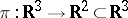 be the projection
  . The order of a point
  is defined as the number of elements in the set
  . A point of order two is called a double point and a point of a order
  a multiple point. One says that a polygonal link
  is situated in regular position if: 1) all its multiple points are double and their number is finite; and 2) no double point is the image of a vertex. Every link may be transformed into regular position by an arbitrarily small rotation of space. If
  is in regular position, then for each double point the branch lying above it (in the direction of the
  -axis) is called an overpass and the branch lying below it an underpass. In order to give a diagram of a link in regular position, it is necessary to give its projection
  and cut the image of an underpass at double points (cf. Fig. a). underpass overpass
Figure: k055570a
If the link is oriented, i.e. a manner for traversing each component is given, one indicates this by arrows in the diagram  . If for this traversal of every component of a link the overpasses and underpasses in its projections alternate, the diagram is called alternating. A link having at least one alternating diagram is called an alternating link (cf. Alternating knots and links).
Every domain  into which the projection of a link divides the plane
  has a corresponding index
  , equal to the sum of the number of circuits accomplished by the projection of each component of the link about an interior point of
  . By transition to an adjacent domain the index changes by 1, which implies that every domain
  may be coloured black or white like a chess board.
In the set of all diagrams in the plane an equivalence relation may be introduced, where two diagrams are called equivalent if and only if the links corresponding to them are isotopic (cf. Isotopy). This makes it possible to reduce the study of knots to plane topology. Thus  if
if  may be obtained from
  by applying a finite number of the elementary operations I–III shown in Fig. band isotopic deformations.
Figure: k055570b
The approach to knot theory established in this way is typical of combinatorial topology. It arose in the first period of development of knot theory (roughly up to the 1940's). In the framework of this approach invariants of knots were defined starting from diagrams and it was then proved that the result did not depend on the choice of a diagram (cf. [1]). In the modern development the definition of invariants is preferably given in terms of algebraic topology, which strips it in first instance from the geometric essence.
The diagram of an oriented link is used in the construction of its Seifert surface. Let  be any point, not double, of an oriented diagram
  of a link
  . The diagram
  is traversed in the direction of the given orientation, starting at
  . At the first encounter of a double point a turn is effected and the motion is continued in the direction of the orientation of
  until one returns to
  ; thus one has described a simple closed contour, called a Seifert circle. The diagram
  is divided into these Seifert circles,
  , which can only touch each other. For each circle
  one denotes by
  the disc lying in a plane parallel to
  such that its boundary projects onto
  . For each double point
  one considers the rectangle
  placed vertically on
  , twisted by
  so that the upper edge lies on the boundary of
  and the lower on the boundary of
  , if
, if  and
and  are the Seifert circles meeting in
  . If each turn is performed to the appropriate side, then the boundary arising from the surface
 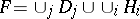 is isotopic to the link
  . The surface so obtained is orientable. A simpler, but possibly unorientable, surface spanned by the link may be obtained by putting a disc over each black area of the chess board diagram and adding, as above, turns through right angles.
Various methods are known for describing the presentations of the group of a link by its diagram. In order to obtain the Wirtinger presentation one considers the set of connected components  of the diagram of a link (the set of overpasses), numbered in the order of crossing each component of the link in the direction given by the orientation. Let
  be a certain symbol associated with
  . For each double point one has
  or
or  , depending on whether the diagram of the link in a neighbourhood of this double point has the form shown in Fig.3aor Fig.3b. The group given by the presentation with generators
  (one for each overpass) and the above-mentioned defining relations (one for each double point) is isomorphic to the group of the link considered. The presentation so obtained is called the upper Wirtinger presentation. Dually one defines the lower Wirtinger presentation.
Figure: k055570c
Figure: k055570d
To find the Dehn presentation one considers the domains  into which the projection of the link divides the plane and introduces a symbol
  for each domain
  . The symbols
  are taken as generators, while the relations are obtained from traversal starting at the points
  : write in succession the symbols corresponding to the domains touching at
  , where if
  and
and  lie on the left of an overpass, then the degrees of
  and
and  are
are  while
while  and
and  equal
equal  . Moreover, put
  , where
  is the exterior domain.
The use of knot and link diagrams to transform links into closed braids.
(Cf. Braid theory.) Choose a point  outside
  such that the rays issuing from
  contain no double points or segments from
  . A complete traversal of one of the components
  of the link can be effected as long as the corresponding traversal in the projection of
  takes place in one and the same direction around
  . Let
. Let  be the first segment directed oppositely and let a point
  be taken such that the triangle
  , where
  and
and  are the ends of
  , contains
  in its interior and the sides
  and
and  are in general position relative to
  . It can be shown that there is at most one double point on
  . Replace
  in
in  by
by  , where if
  contains no double point or is an overpass, it is supposed that
  and
and  are overpasses at all points of their intersection with
  . If
. If  has an underpass, one takes them to be underpasses. Extend this construction for
  and apply it in succession to all components; then a new diagram for
  is obtained in which the projection of each component goes around
  all the time on the same side, i.e.
  is represented in the form of a closed braid [2].
References
| [1] | K. Reidemeister, "Knotentheorie" , Chelsea, reprint (1948) |
| [2] | J.W. Alexander, "A lemma on systems of knotted curves" Proc. Nat. Acad. Sci. USA , 9 (1923) pp. 93–95 |
Comments
Fig.a1 illustrates the construction of the Seifert surface: after the discs have been inserted, at each "split" double point, one has to insert a twisted band as indicated in Fig.a1.
Figure: k055570e
For a detailed proof of Alexander's theorem that every link can be obtained as a closed braid cf. [a1], Chapt. II.
References
| [a1] | J.S. Birman, "Braids, links and mapping class groups" , Princeton Univ. Press (1975) |
| [a2] | L.H. Kauffman, "On knots" , Princeton Univ. Press (1987) |
| [a3] | R.H. Crowell, R.H. Fox, "Introduction to knot theory" , Ginn (1963) |
| [a4] | D. Rolfsen, "Knots and links" , Publish or Perish (1976) |
Knot and link diagrams. Encyclopedia of Mathematics. URL: http://encyclopediaofmath.org/index.php?title=Knot_and_link_diagrams&oldid=13347